计算机网络实验 配置RIPv2动态网络
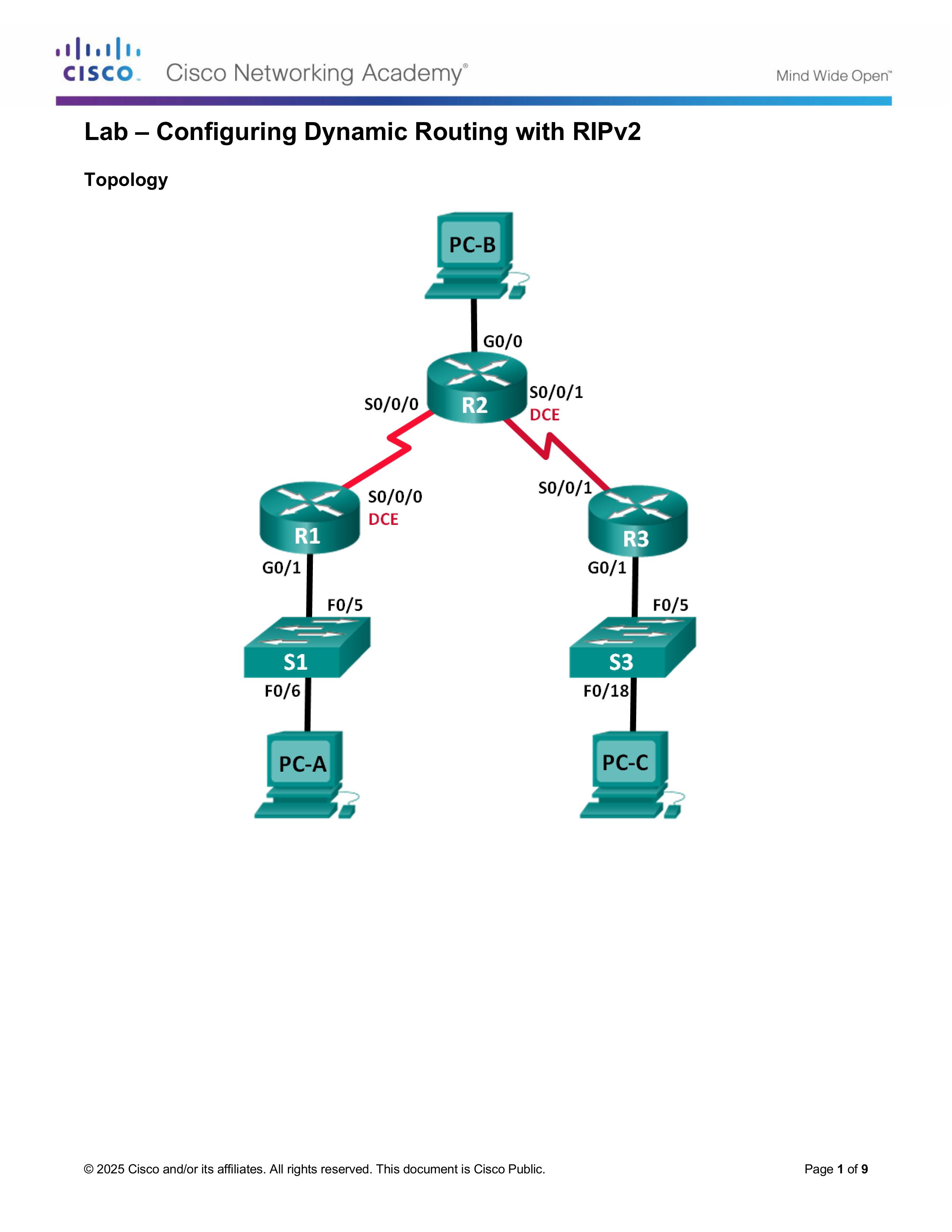
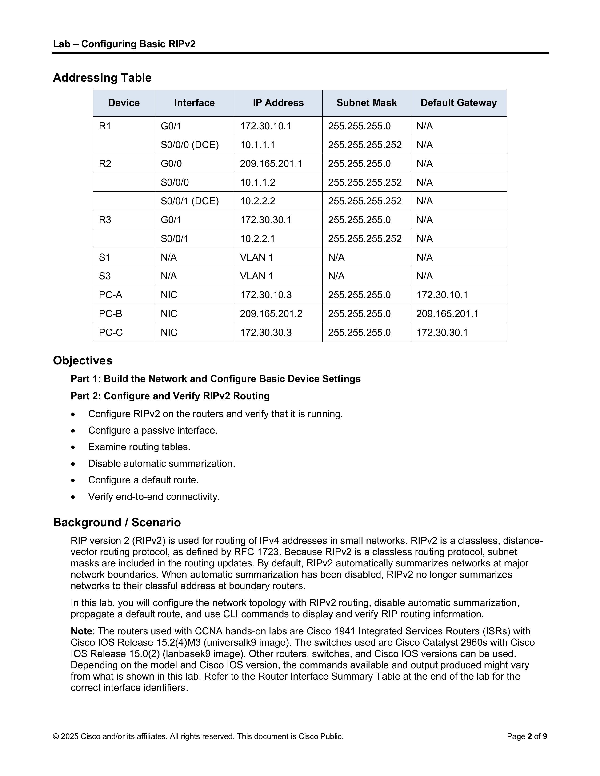
一、要求文档
二、实验要点
想象三个房间(R1、R2、R3),每个房间内的人(PC)只能和本房间的邮差(路由器)说话:
当没有动态路由协议时:
启用 RIPv2 后:
这就是配置RIPv2的作用所在。
三、命令实现
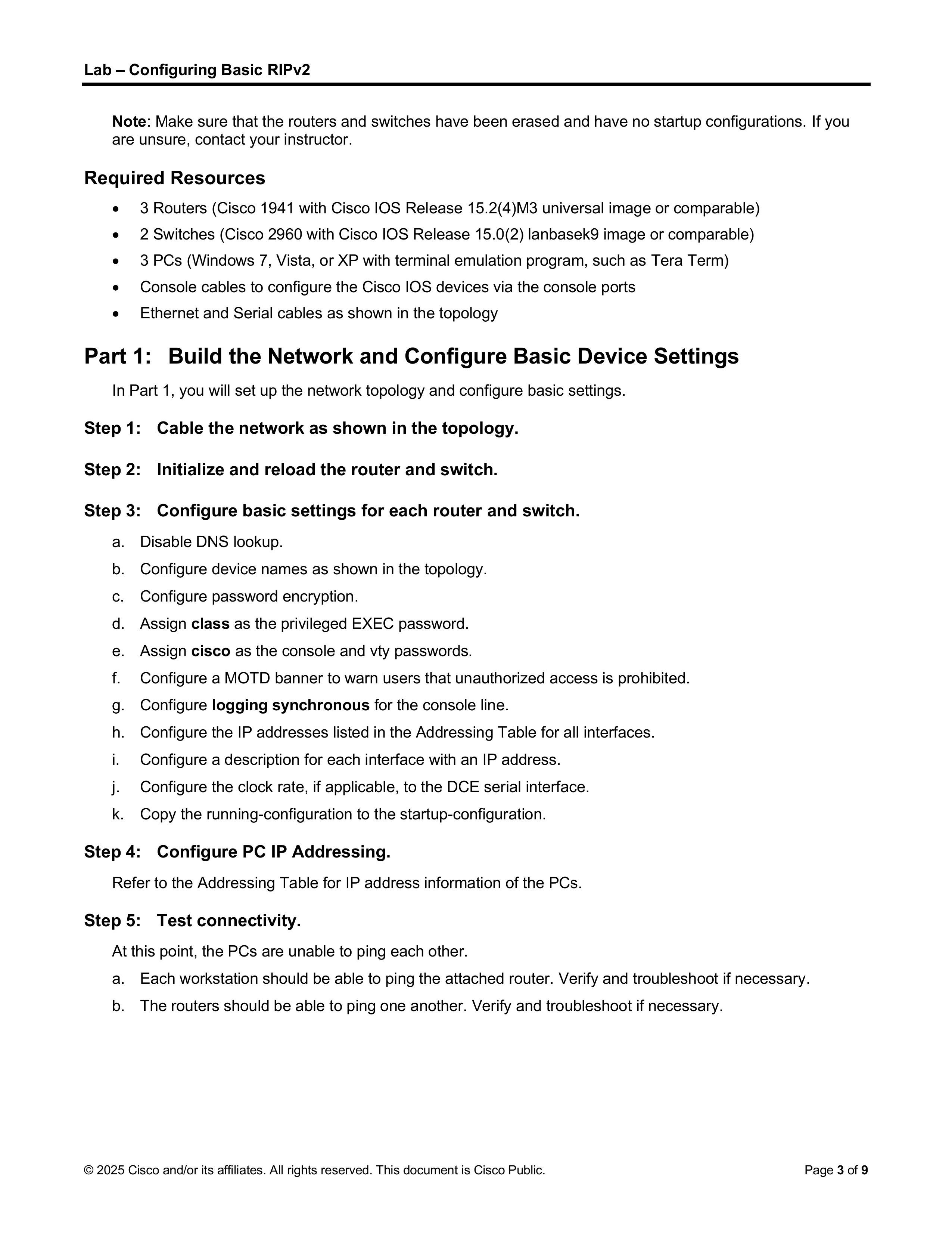
1. Part 1 基础配置
注:Step 1和Step 2的过程省略
1)Step 3 - 配置路由器和交换机地址,以R1为例
在每一个路由器中分别执行以下命令:
1
2
3
4
5
6
7
8
9
10
11
12
13
14
15
16
17
18
19
20
21
22
23
24
25
26
27
28
29
30
31
32
33
34
35
36
37
38
39
40
41
42
43
44
45
46
47
48
49
50
51
52
53
54
55
56
57
58
59
60
61
62
63
64
65
<!-- 进入特权模式 -->
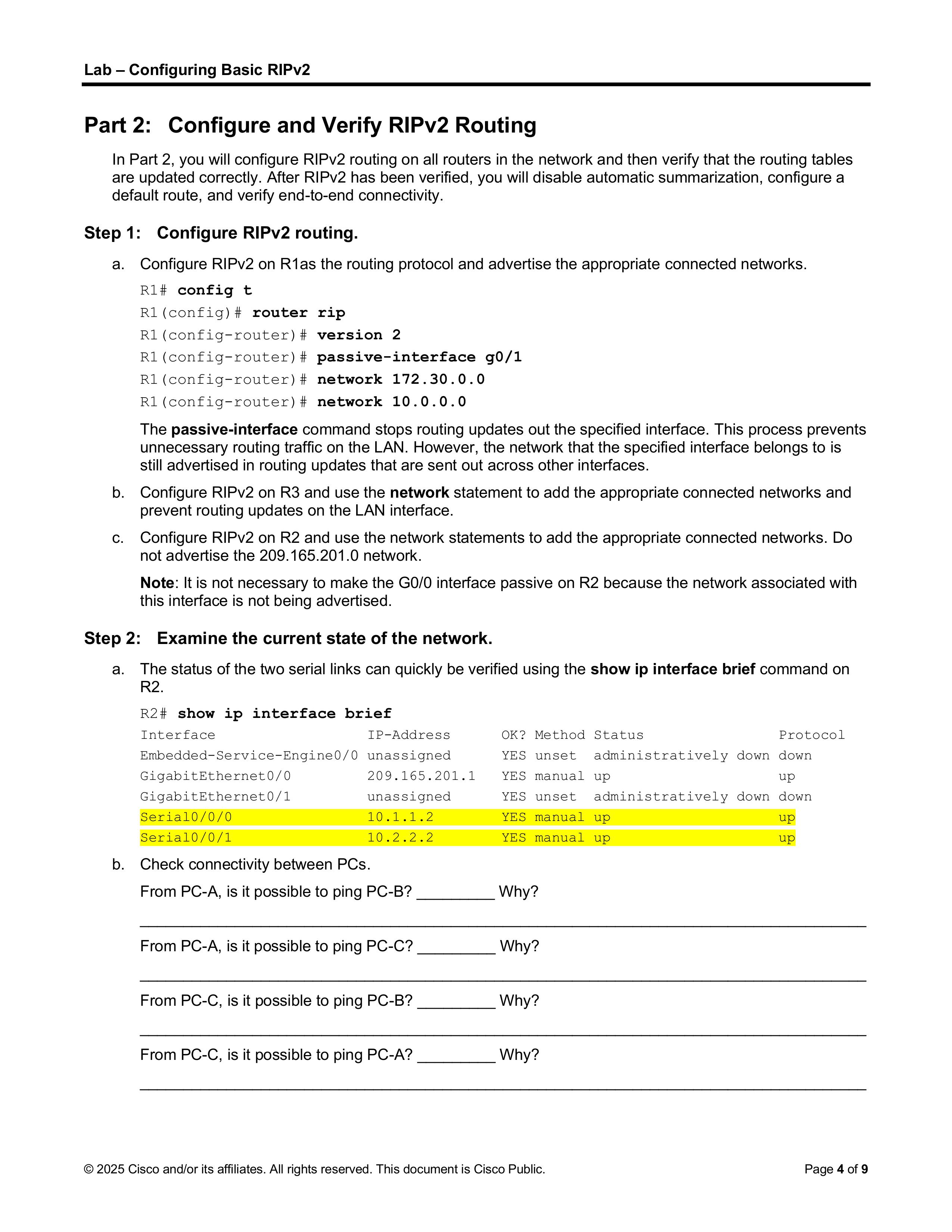
完成以上配置之后,路由器之间应该能相互ping通,PC与对应的路由器端口应该能ping通,但PC之间不行。
因为此时各个路由器的路由表中只包含了直连网络,但是在没有动态路由协议的情况下路由器之间无法交换信息,因此也就无法找到通往远程网络的路径。
动态路由协议是一种自动学习和维护路由表的网络协议,允许路由器之间交换路由信息,并根据网络拓扑变化(如链路故障、新增子网)动态调整数据转发路径,无需管理员手动配置每一条路由。
2. Part 2 RIPv2路由配置
1)Step 1 配置RIPv2路由,以R1为例
执行以下命令:
1
2
3
4
5
6
7
8
9
10
11
12
13
14
15
16
17
18
19
20
21
22
23
24
25
26
27
28
29
30
31
32
33
34
35
R1>enable
2)Step 4 配置默认路由
在R2当中执行以下命令:
1
2
3
4
5
6
7
8
9
10
11
12
13
R2#configure t
这样一来所有互联网流量就可以通过R2统一转发,便于监控和管理。而其它路由器也无需手动配置默认路由,可以通过RIP自动学习。